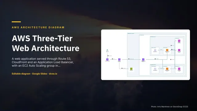
AWS Three-Tier Web Architecture
Slides + PowerPoint5 slides
Free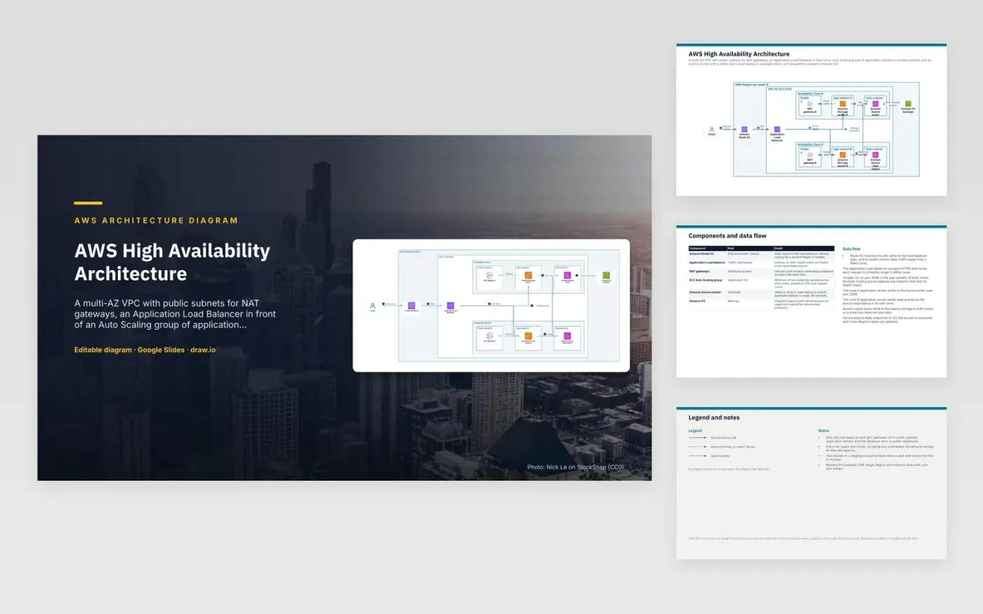
Visitors reach the site by name through Amazon Route 53, which holds an alias to the Application Load Balancer. The balancer distributes HTTP traffic on port 8080 to app servers in private subnets in both zones. The zone A server writes to the Aurora writer, and the zone B server reads from the Aurora replica in its own zone. Aurora copies every write to storage in both zones, and it exports daily snapshots to a versioned S3 bucket.
Public subnets hold just the balancer and the NAT gateways, which leaves application servers and the database without public addresses. Each tier spans two zones, so losing one zone keeps the service running at reduced capacity. To adapt it, replace the example CIDR range and instance sizes, then test failover in a staging account at least twice a year and record the recovery time.
The diagram uses the official AWS architecture icons, each labelled with its service name. AWS, Microsoft Azure and Google Cloud names and icons are trademarks of their respective owners, used here only to describe their services. WorkspaceTemplates is not affiliated with them.
Click Make a copy in Google Slides, then confirm on the Google page. The copy is saved to your own Google Drive.
Rename Users, Amazon Route 53, Application Load Balancer and the other boxes inside AWS Region (eu-west-1) to your own components, and delete the ones your system does not have.
Rewrite the 7-step data flow and the 6-row components table so they match the arrows you keep.
For the draw.io version, download aws-high-availability-architecture-diagram.drawio and open it at app.diagrams.net.
A second zone keeps a copy of the database running if the first zone fails. Aurora stores each write in both zones and can promote the replica to writer, usually in under 30 seconds. A replica in the same zone would be lost with the writer during a zone outage.
Private application servers send outbound traffic, such as calls to package repositories or external APIs, through the NAT gateway in their own zone. Using one per zone means outbound access continues if the other zone fails. A single shared gateway would be a single point of failure.
The load balancer sends regular requests to a health path, here /health, and stops routing to targets that fail. The Auto Scaling group then replaces instances that fail their health check. Health checks therefore handle both traffic steering and instance replacement.
More Google Slides templatesMore developer workflows templates
Slides + PowerPoint5 slides
Free
Slides + PowerPoint5 slides
Free
Slides + PowerPoint5 slides
Free
Slides + PowerPoint5 slides
Free
Slides + PowerPoint5 slides
Free
Slides + PowerPoint5 slides
Free
Slides + PowerPoint5 slides
Free
Slides + PowerPoint5 slides
Free
Slides + PowerPoint5 slides
Free