Network Topology Diagram
Slides + PowerPoint5 slides
Free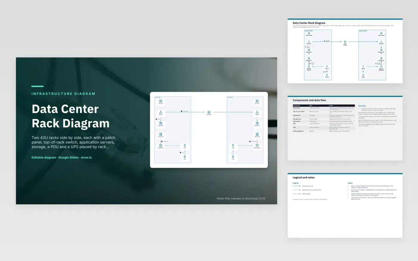
Each rack has a patch panel at the top, a top-of-rack switch and two 2U application servers with dual 25 GbE NICs. Each switch uplinks to a core switch at 100 GbE, so either rack can reach the other. The first server in each rack reaches its storage array over iSCSI on 25 GbE. Power runs from each UPS to its PDU and then to the device, with feed A and feed B on separate circuits. A backup appliance pulls nightly copies from rack B.
The layout is built around the maintenance and cabling problems that cause most outages. The UPS sits at the bottom to keep weight low, and rows run top to bottom from the top of the rack. Fibre and copper go in separate trays, and power cables are kept away from data cables. Each rack keeps a spare rack unit beside the switch for patch cords. A denser build would swap in larger servers, and the power budget per PDU would need rechecking before go-live.
Click Make a copy in Google Slides, then confirm on the Google page. The copy is saved to your own Google Drive.
Rename Patch panel, Switch A, App server A1 and the other boxes inside Rack A (42U) to your own components, and delete the ones your system does not have.
Rewrite the 5-step data flow and the 8-row components table so they match the arrows you keep.
For the draw.io version, download data-center-rack-diagram.drawio and open it at app.diagrams.net.
Two feeds on separate circuits let a rack keep running if one circuit fails. Each server with dual power supplies connects one cord to each PDU. The load on each feed must stay within its share of capacity, so one feed can carry everything if the other fails.
The UPS should carry the full rack load long enough to start a generator or shut down safely. A 3 kVA online unit with about 10 minutes of runtime suits a short outage in this layout. Size it from the measured load, not the nameplate figures, and check the runtime at that load.
A top-of-rack switch sits in the same rack as the servers it connects. Each server runs a short cable to it, which keeps copper runs short. The switch then uplinks to a core switch over faster links.
More Google Slides templatesMore developer workflows templates
Slides + PowerPoint5 slides
Free
Slides + PowerPoint5 slides
Free
Slides + PowerPoint5 slides
Free
Slides + PowerPoint5 slides
Free
Slides + PowerPoint5 slides
Free
Slides + PowerPoint5 slides
Free
Slides + PowerPoint5 slides
Free
Slides + PowerPoint5 slides
Free